
Dev Kit L1
Gimbal development, finally open.
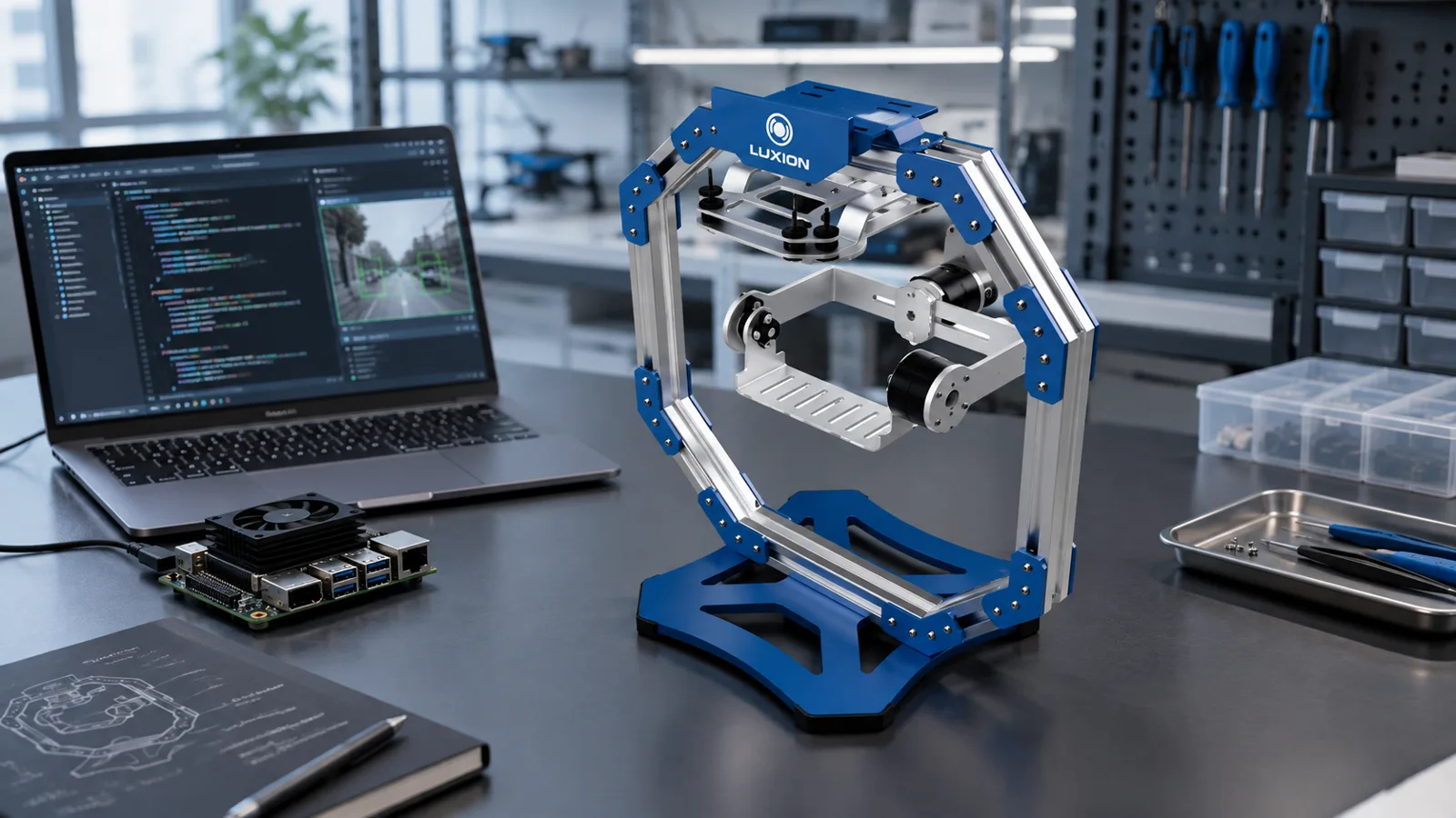
An open 3-axis gimbal platform — hardware, firmware and CAD — so you can build, tune and test your own payloads from day one.
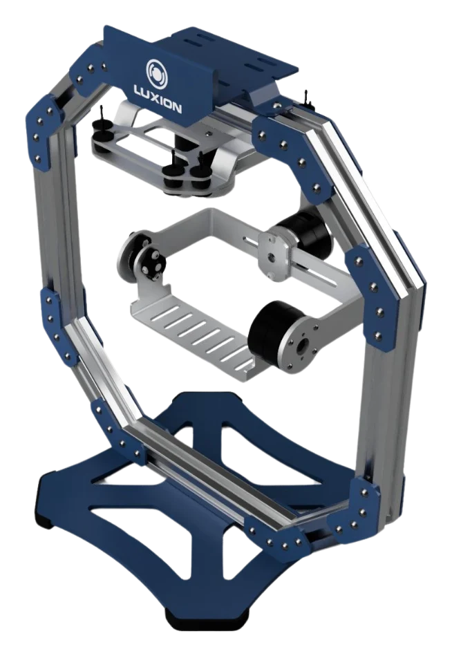
Most gimbals are black boxes. This one isn’t.
Off-the-shelf gimbals hide their control loop, firmware and mechanics. Dev Kit L1 opens every layer — so you learn, modify and build on it instead of working around it.
- Closed firmware, fixed tuning
- No schematic or CAD to build from
- Proprietary protocol, limited integration
- Sealed unit — nothing to learn from
- Open-source firmware on a public GitHub repo
- Schematic and CAD (STEP / DXF) included
- MAVLink, UART, S.Bus and a documented serial protocol
- You assemble it — and understand every part
Three parts. Every one of them open.
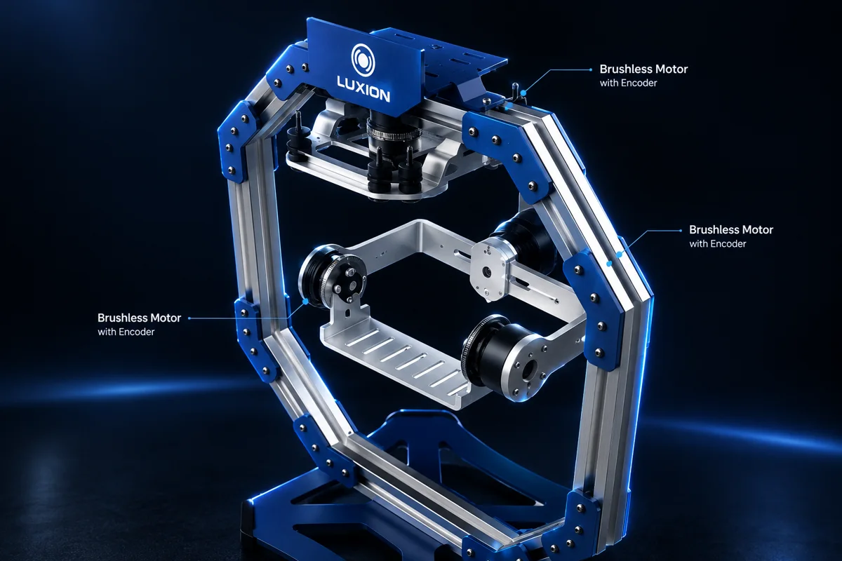
Gimbal frame
- Axes
- 3-axis (Pan / Tilt / Roll)
- Motors
- Brushless gimbal Ø33.5 × 15.3 mm, ~0.06 N·m @12V
- Encoders
- 14-bit magnetic (16,384 counts/rev), SPI, closed-loop
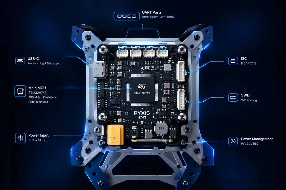
Control mainboard
- MCU · Drive
- STM32G431 · FOC, 3 independent axes
- Sensing
- Dual IMU
- Expansion
- UART, I2C · Debug SWD / JTAG · 5V / 12V out for your payload
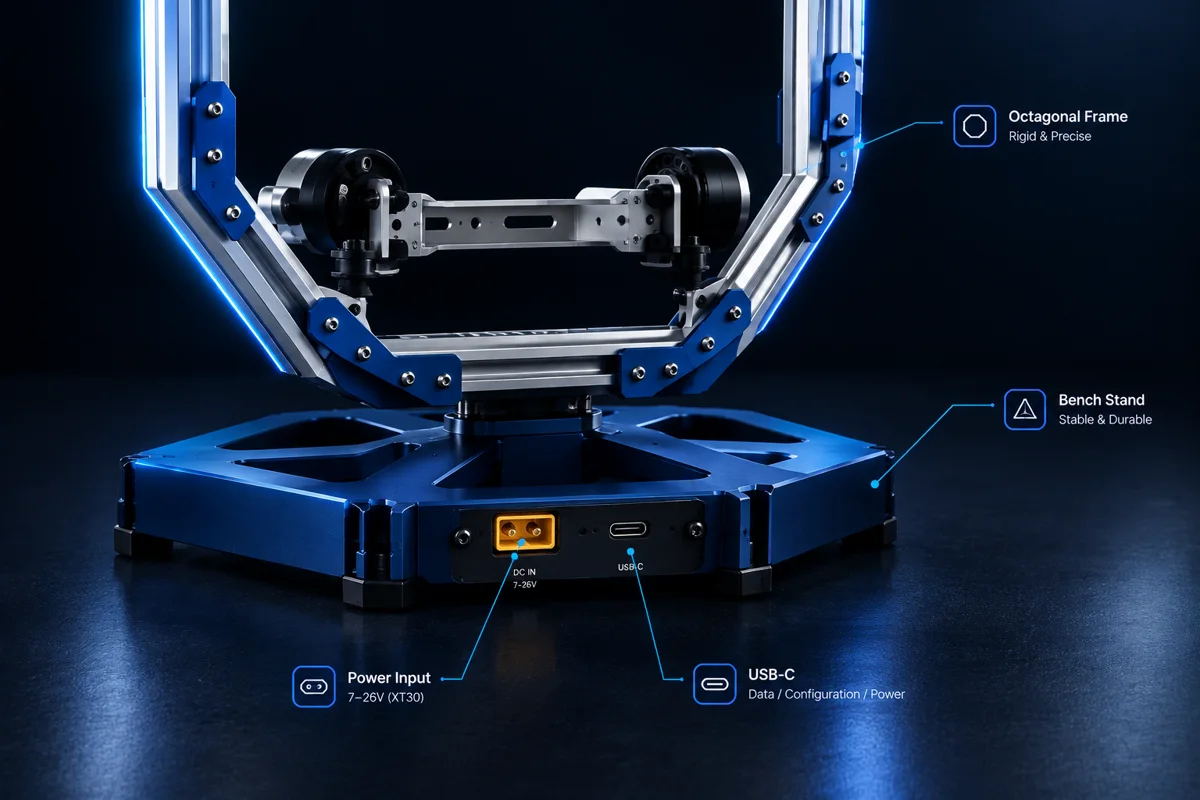
Bench stand
- Structure
- Octagonal aluminium extrusion ring, fully detachable
- Base
- Integrated power input + USB-C / UART
- Size · Weight
- 145 × 90 × 148 mm · ~480 g
Fork it. Tune it. Ship it.
Everything you need to understand and modify the gimbal lives in one public repository — from the motor control loop to the mechanical drawings.
- Firmware sourcePublic GitHub repo
- HardwareSchematic · CAD (STEP / DXF)
- DocumentationProtocol spec · Firmware build guide
- Sample codeGimbal bring-up · GStreamer · YOLO
devkit-l1/
├── firmware/     STM32G431 · FOC · encoders
├── hardware/     schematic · CAD (STEP / DXF)
├── docs/         protocol spec · build guide
│                assembly guide
└── examples/
    ├── gimbal-bringup/
    ├── camera-gstreamer/
└── yolo-detection/Assemble it. Understand it.
Dev Kit L1 ships as a kit. A step-by-step assembly guide takes you from parts to a self-balancing gimbal — and teaches you how it works along the way.
- 01Build the standAssemble the octagonal aluminium ring and base.
- 02Mount the gimbalFit the 3-axis frame, motors and encoders.
- 03Wire the mainboardConnect the controller, IMUs and cables.
- 04Power upPre-flashed firmware self-balances the gimbal.
- 05Start developingRun the samples, then make it your own.
Plugs into the stack you already use.
Autopilots
MAVLink (PX4 / ArduPilot), UART, S.Bus, plus a documented serial protocol.
Companion compute
Raspberry Pi and NVIDIA Jetson compatible.
Blockcam 5x / 10x
CNC metal housing. LAN by default, USB 3.0 or HDMI optional.
Laser module
Visual alignment of the gimbal’s aiming direction.
Start where you are.
Base
For teams with their own controller.
- 3-axis frame
- Brushless motors
- 14-bit encoders
Controller
For firmware and control development.
- Everything in Base
- Control mainboard
- Dual IMU
- Full cable set
Ready-to-Dev
Everything to see and track on day one.
- Everything in Controller
- Power supply
- Blockcam 5x / 10x
- Laser alignment module
- Full sample code
Full specifications
- Axes
- 3-axis (Pan / Tilt / Roll)
- Motors
- Brushless gimbal Ø33.5 × 15.3 mm, torque ~0.06 N·m @12V
- Encoders
- 14-bit magnetic (16,384 counts/rev), SPI read, closed-loop control
- Camera payload
- 150 – 350 g
- Size / weight
- 145 × 90 × 148 mm / ~480 g
- Bench stand
- Octagonal aluminium extrusion ring, detachable; base with integrated power input + USB-C / UART
Target specifications. Subject to change.
Prototype on the kit. Scale with LUXION.
When your payload is ready to fly, our engineers turn it into a production-grade gimbal through custom engineering (NRE) or joint R&D.
Questions
Request a quote
Tell us which kit you need and how many. We’ll reply with pricing and lead time within [2 business days].